Typical circuit diagram of Star Delta starter


S0 = ‘OFF’ Push button
S1 = ‘ON’ Push button
K1 = Line contactor
K2 = Star contactor
K3 = Delta contactor
K4 = Star delta timer (7PU60 20)
F2 = Overload relay
F1 = Backup fuse
F3 = Control circuit fuse


This is a starting method that reduces the starting current and starting torque. The device normally consists of three contactors, an overload relay and a timer for setting the time in the star-position (starting position). The motor must be delta connected during a normal run, in order to be able to use this starting method. The received starting current is about 30 % of the starting current during direct on line start and the starting torque is reduced to about 25 % of the torque available at a D.O.L start. This starting method only works when the application is light loaded during the start. If the motor is too heavily loaded, there will not be enough torque to accelerate the motor up to speed before switching over to the delta position. When starting up pumps and fans for example, the load torque is low at the beginning of the start and increases with the square of the speed. When reaching approx. 80-85 % of the motor rated speed the load torque is equal to the motor torque and the acceleration ceases. To reach the rated speed, a switch over to delta position is necessary, and this will very often result in high transmission and current peaks. In some cases the current peak can reach a value that is even bigger than for a D.O.L start. Applications with a load torque higher than 50 % of the motor rated torque will not be able to start using the start-delta starter. 

Wiring of Star Delta Starter with Timer Control Panel


PLC Program for Star Delta Starter 


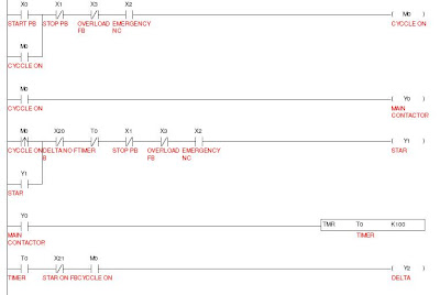
Note:Only for Simulation.
Read More..

Diffrence between PLC and DCS


The traditional system, monitoring processes across multiple locations, involved the collection of data to a single location. This is what SCADA does, basically the "DA(data acquisition)" portion of SCADA. Some control was usually present but not a significant amount. The modern "DCS", or distributed control system, could be described by taking each word of the acronym out and explaining it. 

First, Distributed implies that the functions are all distributed at various locations. These functions refer to the data collection, processing, controlling outputs, alarming, collecting historical data, etc. In a typical DCS system, you will find physical boxes that handle each of the above functions (well, almost). There is additionally an implication about geographical distribution, or that the functions can be distributed in different physical locations. This is a benefit in that prevents failure in one part of the system from affecting another part.

The word Control implies the ability of the system to close the loop between an input measurement and a manipulated handle in the process. This means that the DCS shall have the capability for basic and advanced control algorithms.

The word System implies that all of the above is connected as one contiguous system i.e. in simple words, one comprehensive system with systems and physical parts spread over potentially a wide area carrying out monitoring and control functions.

A control system may have one or more PLCs (programmable Logic Controllers). The PLC is a term applied in different ways. In large process facilities, there is a requirement that there be two systems-one for control while another for safeguarding. The plant-wide safeguarding portion is typically done by a safety-certified PLC. However, smaller PLCs could be used in smaller single loop control and safeguarding applications as well.

PLC Simplified with limited logic control for like a machine or Simple process with limited interlock logic - progamme can be modified easily.This will give only indication of failure.No recording the event or process parameter ,with limited memory.Cost wise it is very cheap.

DCS concern Huge multiple logic controlls with  greater than 1000 of inter lock for process of power plant or refineries or any process Industries it will give all types of alarm in soft copy & hard copy about process , failure & record all the process input & out put parameters & efficiency if required .(Boiler,Turbine, Generator controlls Switch gear cotrolls ie power generation to Transmission.) Very Large memory back up, failuer rate very less,process parameter all are fixed cannot be changed by Individual. Troubleshooting very easy . Production will not be affected at all. 

 Fully integrated DCS System:   


The ADVANTAGES were greatly reduced wiring costs, much more limited failure and less cost to add more points.   The DISADVANTAGES were that wiring costs were that wiring costs were still significant and there was lack of interoperability among controllers of various manufacturers due to the proprietary protocols. Hence the user was locked into a single vendor.
Popular DCS Systems Available:
  • Yokogawa – Centum Excel  , CS 3000, CS 5000
  • Fisher - Rosemant - Delta V
  •  Honeywell - TDC 3000, GUS
  • ABB - Freelance 2000
  • Moore -  APACS
  • Fox boro - I/A series             
 

Read More..

Programmable Logic Controller Introduction

PLC (Programmable Logic Controller) is one of electronic equipments. It was called “Sequence Controller” before. It was named “Programmable Logic Controller (PLC)” by NEMA (National Electrical Manufacture Association) in 1978 and defined as electronic equipment. The operation of PLC is explained in the following steps:
Step 1
Read the external input signal, such as the status of keypad, sensor, switch and pulse.
Step 2
Using microprocessor to execute the calculations of logic, sequence, timer,counter and formula according to the status and the value of the input signal read in the step 1 and pre-write programs saved inner to get the corresponding output signal, such as open or close of relay, operation of controlled machine or procedure to control automatic machine or procedure of manufacture. PLC also can be used to maintain and adjust of production program by editing or modifying the peripheral equipments (personal computer/handheld programming panel). The common program language of PLC is ladder diagram. There are stronger functions in PLC with the development and application requirements of electronic technology, such as position control, network and etc. Output/Input signals are DI (Digital Input), AI (Analog Input), PI (Pulse Input), DO (Digital Output), AO (Analog Output) and PO (Pulse Output). Thus PLC plays an important role in the feature industry.
In todays environment of automation, the importance of PLC has rapidly increased. With growing demand for training in this area, Different companys has introduced several packages for PLC training. The standard package consists of PLC module, power supply, programming and operating software and PC/PPI cable. An optional accessory includes digital and analog expansion modules.

PLC Performs following functions.

  • PLC performs relay equivalent functions
  • PLC performs ON/OFF control
  • Ladder diagram programming
  • Designed for industrial environment
PLC INPUT Wiring:

  • Push buttons
  • Selector Switches
  • Limit Switches
  • Level Switches    
  • Photoelectric Sensors
  • Proximity Sensors 
  • Motor Starter Contacts 
  • Relay Contacts 
  • Thumb wheel Switches 
PLC OUTPUT wiring 
  • Valves 
  • Motor 
  • Starters 
  • Solenoids 
  • Control 
  • Relays
  • Alarms 
  • Lights 
  • Fans 
Internal Structure of PLC  
 
Selecting PLC hardware

       Inputs/Outputs
      Type,
       AC, DC, sourcing, sinking, etc.
      Number of
       10, 16, 20, 32, 156
       Memory
      Type
       Flash or Battery backed
      Size
       1k, 6k, 12k, 16k, 64k
       Functions required
      Instruction set
       Messaging
       PID
       PTO, PWM
      Arithmetic
      Communications
       DeviceNet, Ethernet
       Remote I/O, DH+
      Report generation


PLC application  

       Solenoid 1
      On  = Sol 3 is off, and Motor is off, and Sensor 2 is off, and Auto Switch is on
      Off  = Sol 3 is on, or Motor is on, or Sensor 2 is on
       Solenoid 2
      On  = Sol 3 is off, and Motor is off, and Sensor 2 is on
      Off  = Sol 3 is on, or Motor is on, or Sensor 1 is on
       Motor
      On  = Sensor 1 is on, and Solenoid 2 is off, and Solenoid 1 is off
      Off  = Solenoid 3 on
       Solenoid 3
      On  = Sol 1 is off, and Sol 2 is off, and Motor has run for 30 sec.
      Off  = Solenoid 3 has been on for 60 sec.
Read More..

Basic PLC Ladder Programming Example 14


Basic PLC Ladder Programming Training Example 14 : 24 Hour clock using Counter PLC Ladder Program 

Basic PLC Ladder Programming Training Examples for Beginners. Hi Friends here we are starting a series of Free Training on PLC Ladder Programming. These PLC Ladder Programs are important to get basics of Ladder Programs


PLC Ladder Practice Problem:


  •  Using 3 counters together with the flag of M1013 (1s clock pulse) to operate a 24-hour clock. 

Topics Covered in this example is use of Counter in PLC Program  

Number of PLC Counter Required 

C0 - count per second
C1- count per minute
C2 - count per hour 

Number of PLC internal memory flag Required

M1013 - 1s clock 

PLC Ladder Programming:


PLC Ladder Programming Description: 

.
  • The key of operating a 24-hour clock is to use M1013 (1s clock pulse). When the program is executed, C0 will count once per second. When the counted number reaches 60(1 minute), C0 = ON. C1 will count once, and C0 will be reset at the same time; similarly, when the counted number in C1 reaches 60(1 hour), C1 = ON. C2 will count once, and C1 will be reset at the same time. Furthermore, when the present value in C2 reaches 24, C2 will be reset, and the 24-hour counting process will start again.
  • The 24-hour clock operates by using C0 to count “second”, C1 to count “minute” and C2 to count “hour.” In this clock, the value of “second”, “minute” and “hour” can be read by C0, C1 and C2 correspondingly. When the set value of C2 is 12, the clock will be a 12-hour clock.  

See More Examples here


PLC Ladder Programming Example 1
PLC Ladder Programming Example 2
PLC Ladder Programming Example 3
PLC Ladder Programming Example 4
PLC Ladder Programming Example 5
PLC Ladder Programming Example 6
PLC Ladder Programming Example 7
PLC Ladder Programming Example 8
PLC Ladder Programming Example 9
PLC Ladder Programming Example 10
PLC Ladder Programming Example 11
PLC Ladder Programming Example 12
PLC Ladder Programming Example 13
PLC Ladder Programming Example 14
PLC Ladder Programming Example 15


    Read More..