PLC (Programmable Logic Controller) is one of electronic equipments. It was called “Sequence Controller” before. It was named “Programmable Logic Controller (PLC)” by NEMA (National Electrical Manufacture Association) in 1978 and defined as electronic equipment. The operation of PLC is explained in the following steps:
Step 1
Read the external input signal, such as the status of keypad, sensor, switch and pulse.
Step 2
Using microprocessor to execute the calculations of logic, sequence, timer,counter and formula according to the status and the value of the input signal read in the step 1 and pre-write programs saved inner to get the corresponding output signal, such as open or close of relay, operation of controlled machine or procedure to control automatic machine or procedure of manufacture. PLC also can be used to maintain and adjust of production program by editing or modifying the peripheral equipments (personal computer/handheld programming panel). The common program language of PLC is ladder diagram. There are stronger functions in PLC with the development and application requirements of electronic technology, such as position control, network and etc. Output/Input signals are DI (Digital Input), AI (Analog Input), PI (Pulse Input), DO (Digital Output), AO (Analog Output) and PO (Pulse Output). Thus PLC plays an important role in the feature industry.
In todays environment of automation, the importance of PLC has rapidly increased. With growing demand for training in this area, Different companys has introduced several packages for PLC training. The standard package consists of PLC module, power supply, programming and operating software and PC/PPI cable. An optional accessory includes digital and analog expansion modules.
PLC Performs following functions.
- PLC performs relay equivalent functions
- PLC performs ON/OFF control
- Ladder diagram programming
- Designed for industrial environment
PLC INPUT Wiring:

- Push buttons
- Selector Switches
- Limit Switches
- Level Switches
- Photoelectric Sensors
- Proximity Sensors
- Motor Starter Contacts
- Relay Contacts
- Thumb wheel Switches
PLC OUTPUT wiring

- Valves
- Motor
- Starters
- Solenoids
- Control
- Relays
- Alarms
- Lights
- Fans
Internal Structure of PLC

Selecting PLC hardware
• Inputs/Outputs
– Type,
• AC, DC, sourcing, sinking, etc.
– Number of
• 10, 16, 20, 32, 156
• Memory
– Type
• Flash or Battery backed
– Size
• 1k, 6k, 12k, 16k, 64k
• Functions required
– Instruction set
• Messaging
• PID
• PTO, PWM
– Arithmetic
– Communications
• DeviceNet, Ethernet
• Remote I/O, DH+
– Report generation
PLC application
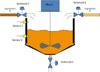
• Solenoid 1
– On = Sol 3 is off, and Motor is off, and Sensor 2 is off, and Auto Switch is on
– Off = Sol 3 is on, or Motor is on, or Sensor 2 is on
• Solenoid 2
– On = Sol 3 is off, and Motor is off, and Sensor 2 is on
– Off = Sol 3 is on, or Motor is on, or Sensor 1 is on
• Motor
– On = Sensor 1 is on, and Solenoid 2 is off, and Solenoid 1 is off
– Off = Solenoid 3 on
• Solenoid 3
– On = Sol 1 is off, and Sol 2 is off, and Motor has run for 30 sec.
– Off = Solenoid 3 has been on for 60 sec.


